The 11 space GroupDIY 511 rack is in its 4th production run, and there are now over 300 units in operation around the world. In the wake the successful launch of this standard within the DIY community, a slew of new designs and kits have emerged. For my part, I simply happened to be exploring the idea of DIY while the rack kit, power supply, power transformer details were being finalized by capable 51X Alliance members in Germany, UK, and the United States.
My build is a 1st generation GroupDIY 51X Alliance complete kit with its 2U rack mount power supply. While the power supply circuit and onboard electronic components have remained the same, the form factor and layout of the power supplies have evolved since my builds. Jeff Steiger from Classic Audio Products is the North America distributor for the current floor-box type power supply kit. Jeff also supplies the 11 space 511 rack kit to North America. Orders outside of North America are handled by sending email to kitorder@51xaudio.com . Currently, the floor box power supply and a dual power supply which incorporates two complete power supply PCB's in a single 2U rack enclosure are available for purchase. Even though the kits have evolved, I felt it is still valuable to post about my 1st generation build the quality of the kit is absolutely uncompromising making the finished product quite timeless. These kits go well beyond the level of "good product" and are truly a point of pride for the people behind them.
I am currently running two 11 space racks and two 1st generation power supplies in studio and quickly running out of space. At this rate, a fully detailed build thread of the current floor box PSU will be happening soon.
As the 511 rack kit was my very first electronics DIY project, there were a few mistakes made, but in the end, the rack turned out quite robust despite my newbie errors. I am glad I got off the sidelines and jumped in with both feet to play with the rest of the kids.
Every journey begins with a first step:
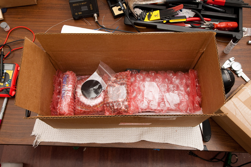
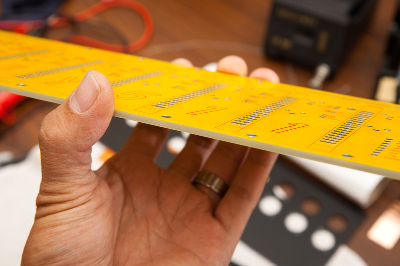
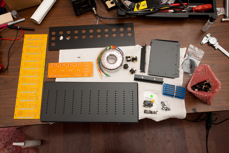
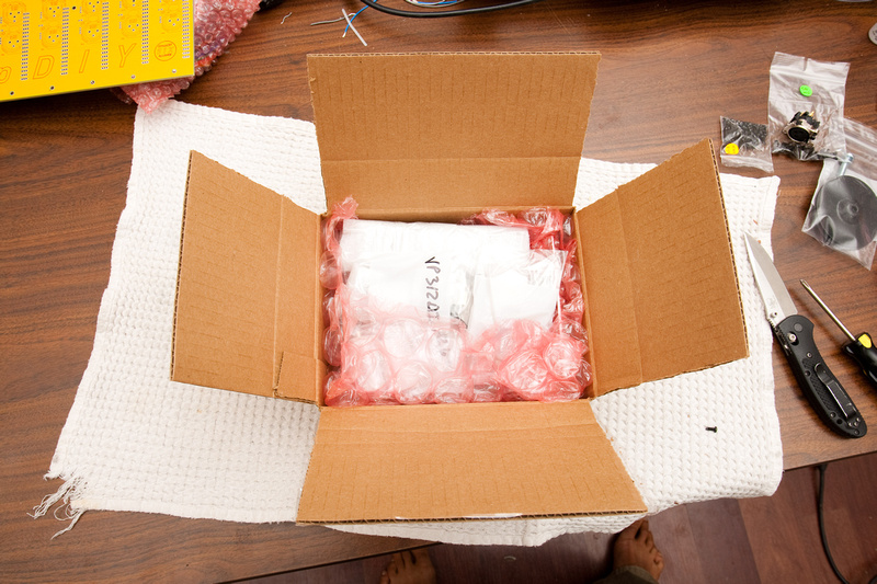
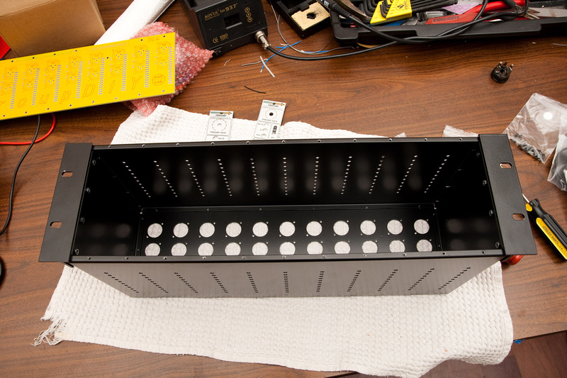
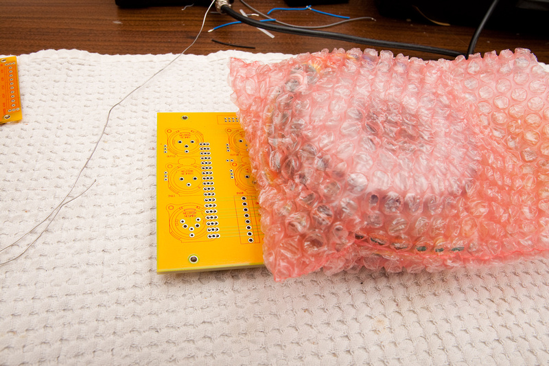
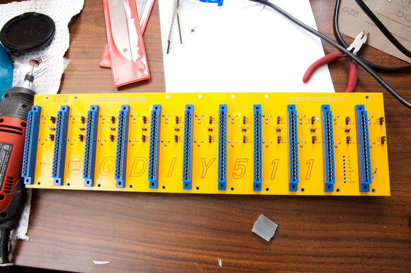
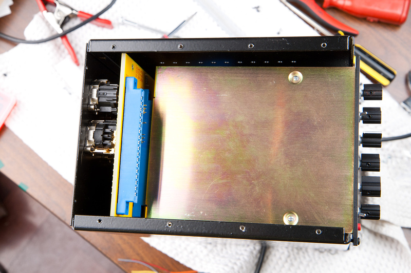
Everything seemed excessively well packed, and I went about seeing what I had. I heard that the rack PCB was thick to reduce flex as modules are inserted and removed, but in person, it's pretty impressive.
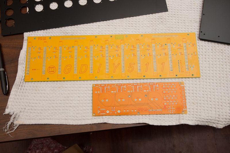
At the time of my rack purchase, the power supply kits were still under development, but the circuit and PCB had already been finalized and were available.
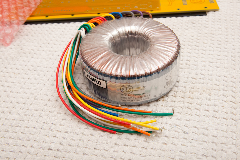
The custom transformer (with the necessary windings to supply +/- 16V, +/- 24V, and 48V) looks massive, and righteously priced to boot. This is the North America variant. Due to the weight and subsequent cost of shipping for power transformers, they were sourced from different vendors for Europe and North America.
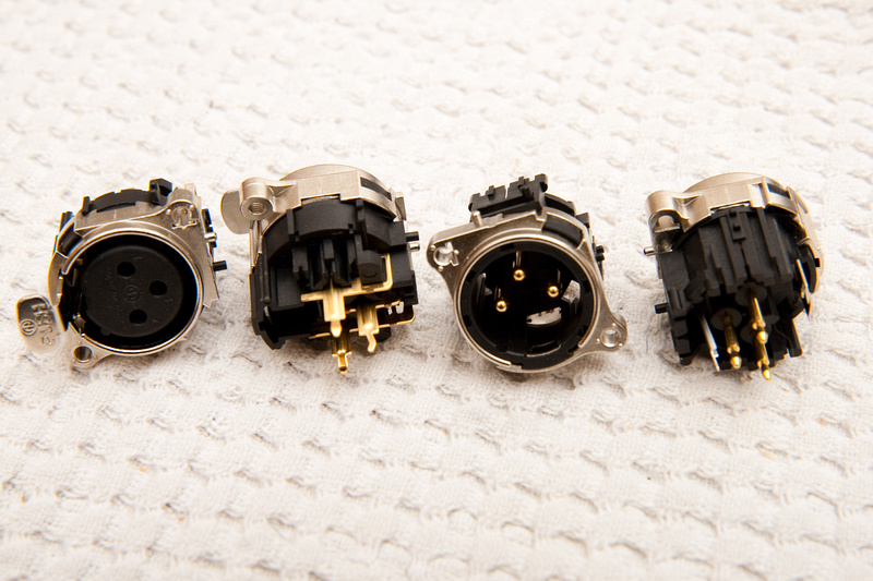
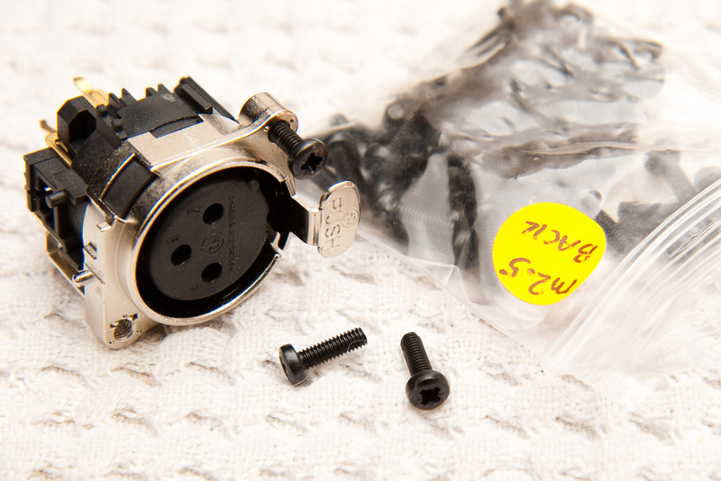
And the little Neutrik connectors seem pretty trick and took some time to source at volume.
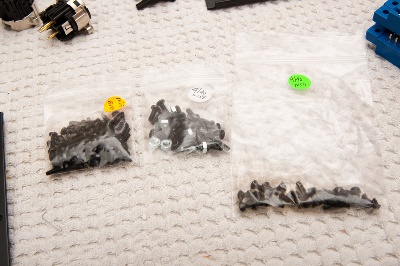
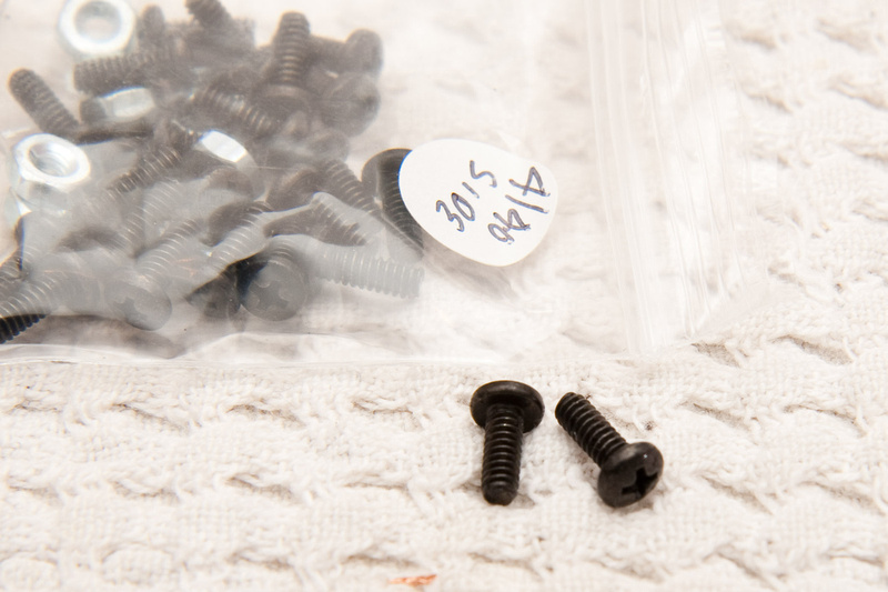
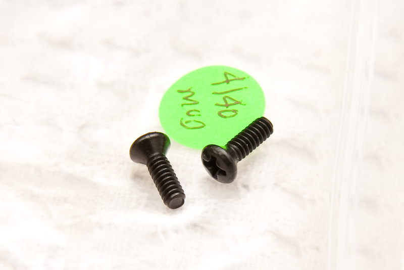
All of the kit screws were well packed and clearly labeled. The only unclear thing was where they all went on the rack.
A big 'ole table of full of confusion for me to try and sort out

No instructions included, but I've shopped at IKEA before, so this shouldn't be impossible to figure out, right?
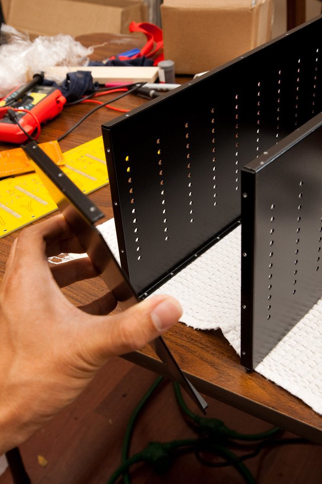
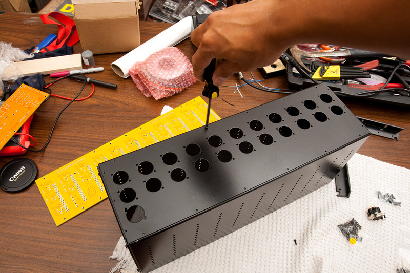
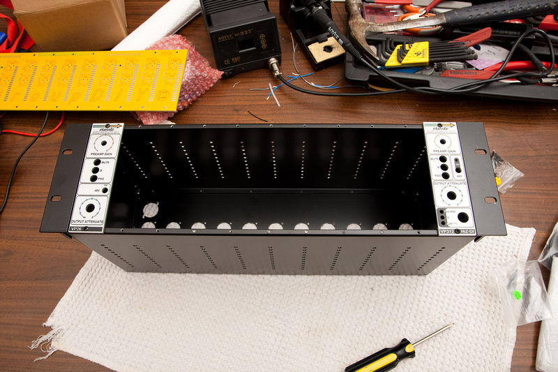
Turning the metal bits around a few times, I determined top and bottom panels are identical, and the front side has holes appropriately spaced for the rack modules to mount.
The side panels have a series of 4 holes near the front face to mount the rack ears. . . so, having oriented myself as to which bits go where, I needed to figure out which screws go where.
These ones (4-40) go on the side panels and the rack ears.
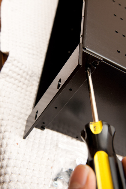
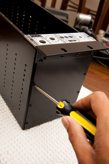
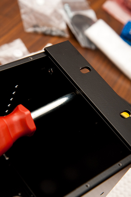
Keeping in mind which side is front and which side is back, but easiest way I could see to start was on a corner like this: (Notice the front side is face down in the picture. . . note on the larger metal (top and bottom pieces) there are fewer holes than on the back which is facing up than the front which is face down. . .and on the side piece, the 4 holes for the rack ears are down towards the white towel)
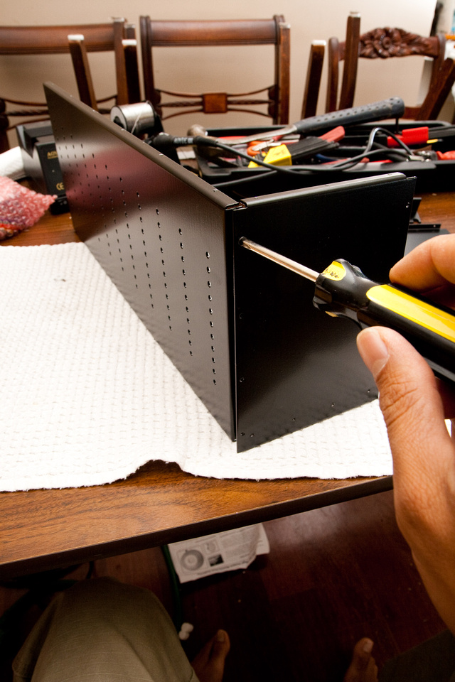
I installed one side with 4 screws installed loosely so the pieces could still shift. That way, I could leave slack for the other panels to align as I screw them together.
Other side. . . same routine. 4 screws loose.

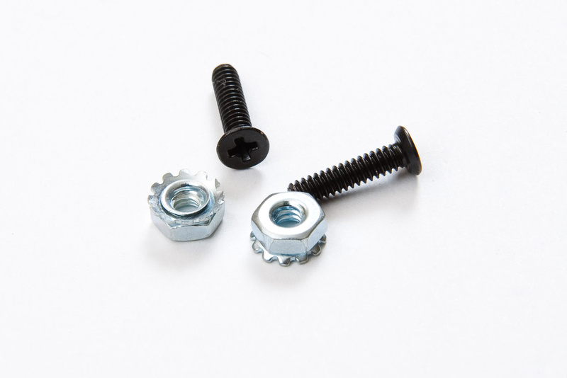
These M2.5 screws are the ones that fit on the back panel. They also fit into the Neutrik connectors.
With the panels installed loosely, I can shift everything around until the holes of the back panel align. I'm not putting all of the screws in yet. . . just enough at the sides and particularly at the corners to align things. I install these screws loosely as well for now.
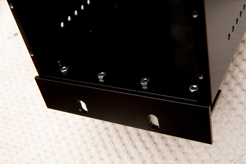
The rack ears don't seem to effect the overall alignment of the enclosure, so I tighten those down to final torque right away using the larger screws that are bagged with the hex nuts.
I had to go dig through my other ordered items because I wanted something to align the front side of the case before I tightened down the side and back screws to lock everything together. I ordered 2 preamp kits from Jeff. . . well . . . because I don't have any 500 series modules, and as pretty as a box is, it'd be pretty boring by itself.
These pan head 4-40 screws are for the front module panels.
Since the face plates that Jeff supplied with his kits have beveled holes, I figure they would be self-aligning. I went ahead and screwed 2 face plates in at the 2 edges of the case to align the front face.
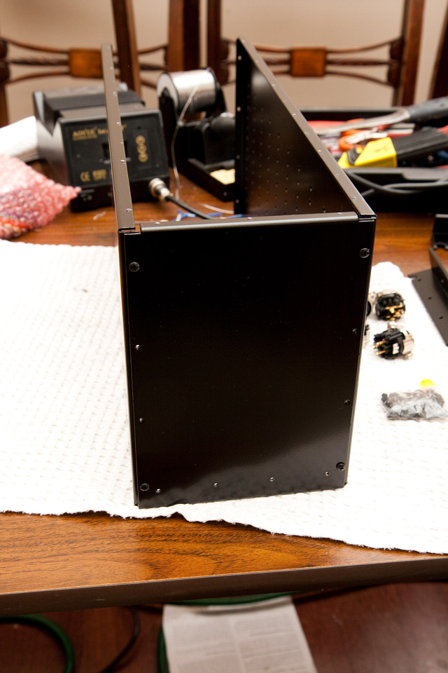
With the front and back panels squaring up my box, I now tighten down the side panel screws to final torque and install all of the screws.
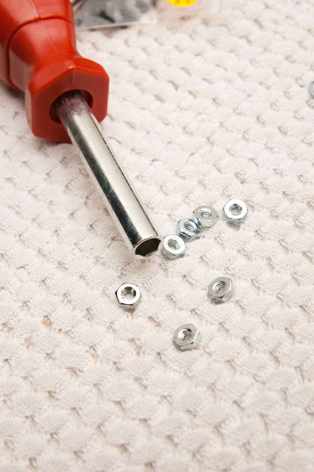
I may be totally wrong about this, but it seems to me the rack ears would bear the brunt of the load when this unit is mounted up, so I assumed the hex nuts are for the 8 rack ear screws. I do not have a small enough socket set to install these, but if you have one of those screwdrivers with interchangeable bits, the nuts fit perfectly in the screwdriver's bit socket.
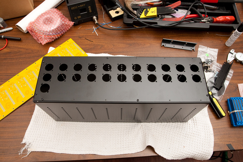
Box assembled. . . Humans win!
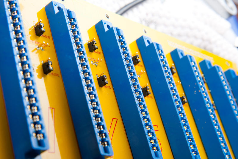
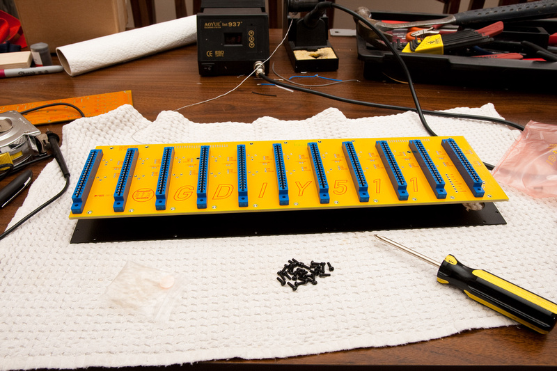
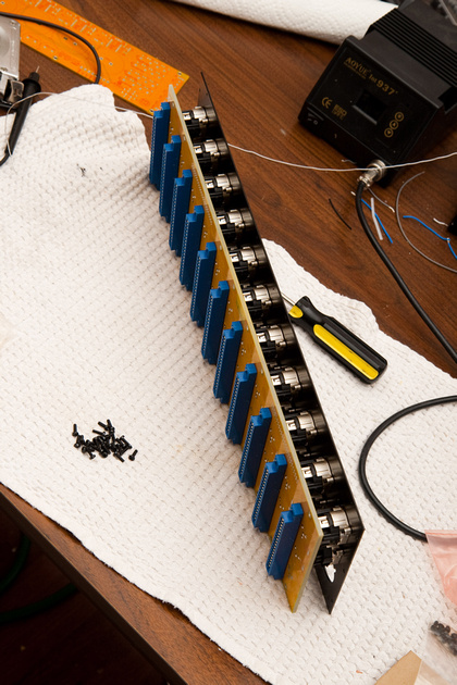
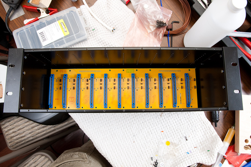
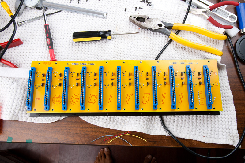
Next, I turn to the backplane PCB. Here, I'm installing the 18 pin edge connectors.
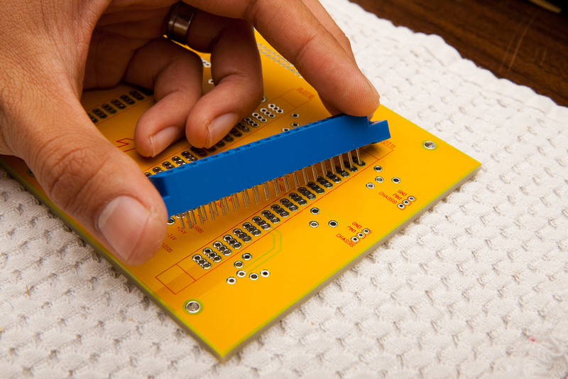
There is a little bit of wiggle on them. . . no that it probably matters, but I tried to center the piece in the holes and the put something on the PCB to hold it in place while I soldered.
Now 10 more!
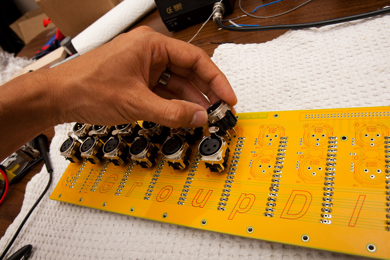
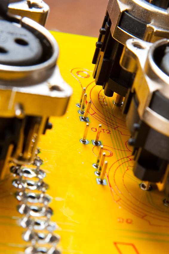
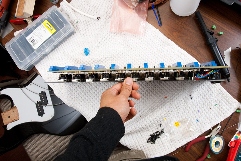
Next I placed the Neutrik connectors is. .. they seem to have a pretty tight tension fit into the PCB. I made sure to seat the connectors all the way to their stops. Do NOT solder yet. It would be an absolute nightmare trying to attach this to the enclosure back panel if they are soldered in at this point.
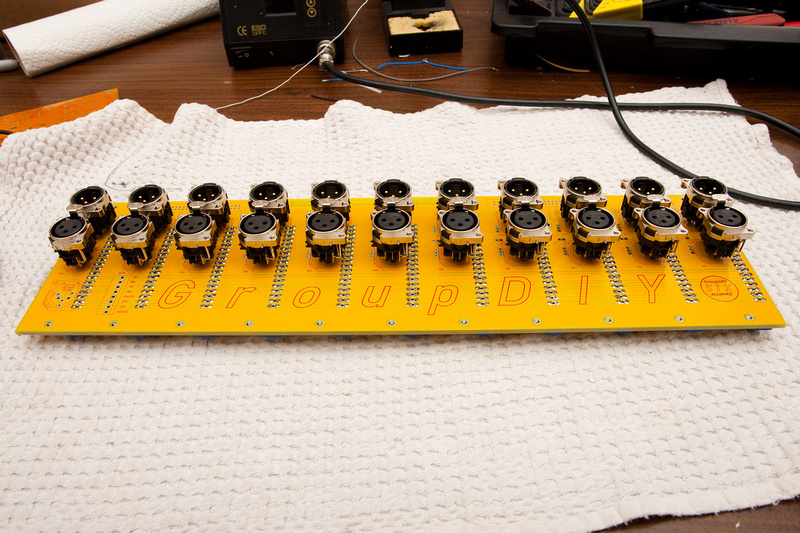
I fit the back panel on to align all the connectors. . . the top row was pretty tight.
Checking to verify that my connectors are still all seated fully to the PCB.
Then, I put all the Neutrik connector screws in. I don't know if that was absolutely necessary as everything seemed aligned pretty well without the screws, but I'm sure it did not do any harm.
Making sure to use these screws
Then, flip the whole thing over.
This is how the pins look from the back side. The PCB is so thick the contact pins barely potrude.
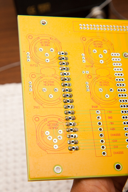
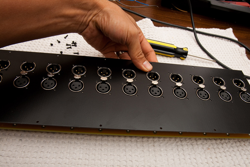
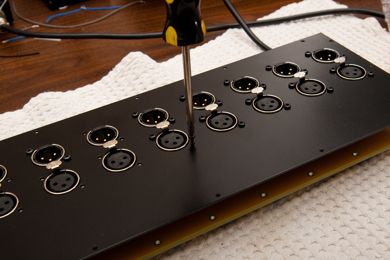
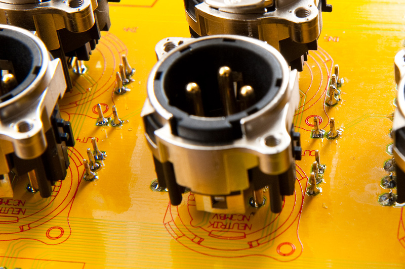
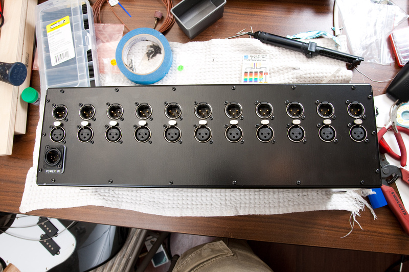
And, with the enclosure back panel attached, solder all of the XLR connectors into the backplane PCB.
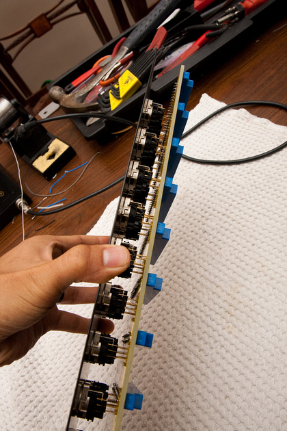
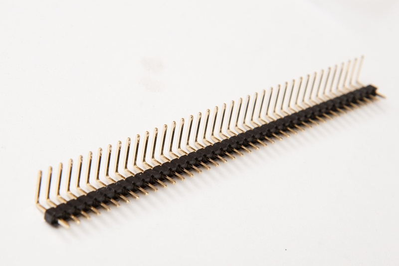
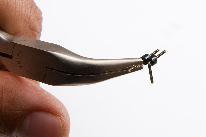
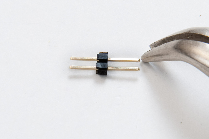
I went to a local Fry's Electronics and picked up a few small do-dads to try and get my rack buttoned up while waiting for PSU parts. What follows is probably not the best way to do things, but the store was out of straight headers, so I purchased some angled ones. I probably would have just bought both if they were available. I remembered reading that some folks has clearance problems with the straight headers on 1 particular 500 series module. . .
These were pretty easy to cut to proper length.
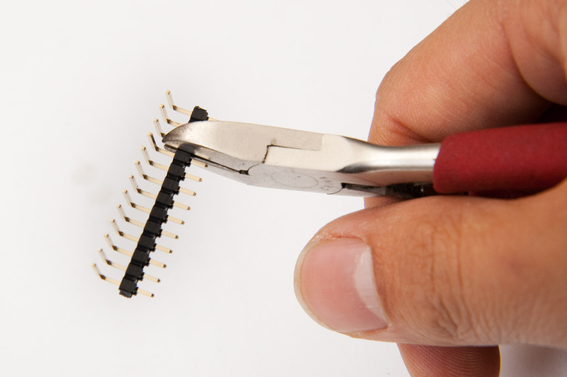
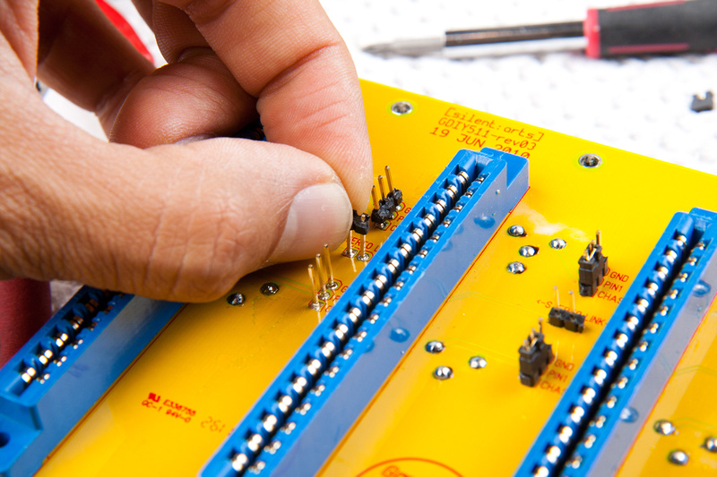
Then, I jammed the little plastic tab down with my thumbs
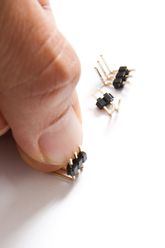
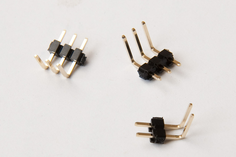
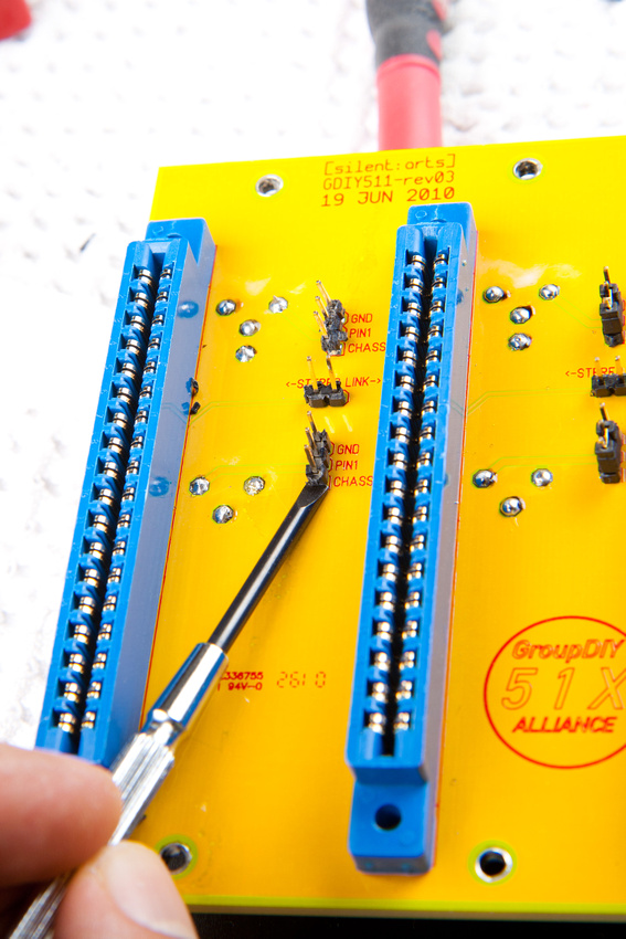
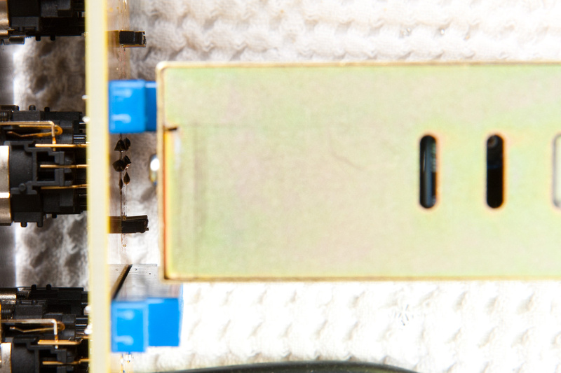
. . .and figured out I probably have a little bit of a clearance problem on the stereo link with this arrangement.
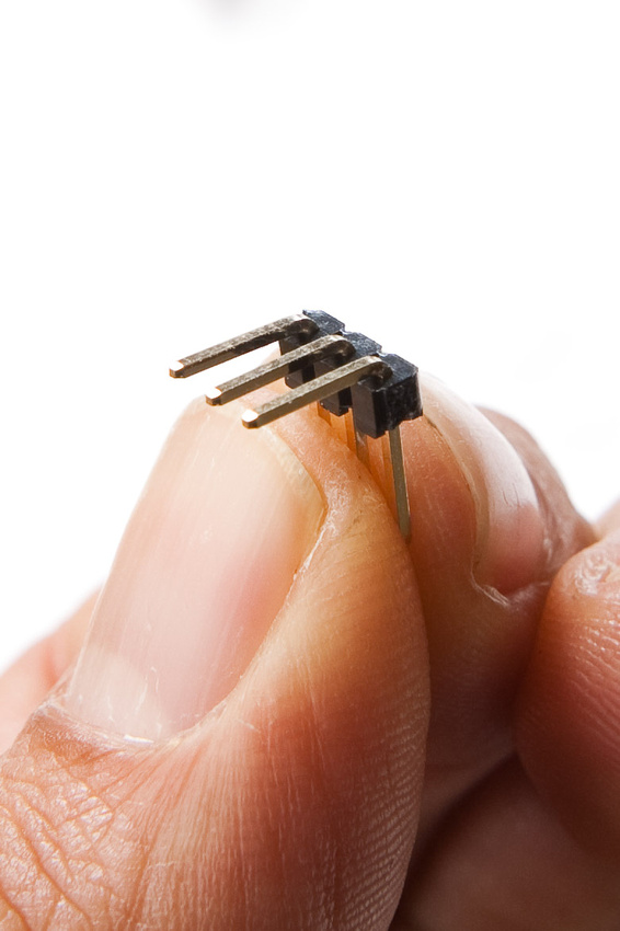
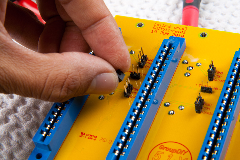
So, because I was in a bit of a hurry, I decided to "hack" the parts to work even though buying a proper straight header would have been the proper way to go. I thought about it for a little while and decided it would be difficult installing and removing the little shunts sideways with my hand deep inside of a rack, so straight up (as designed) seemed the be better.
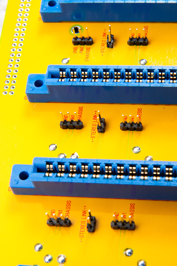
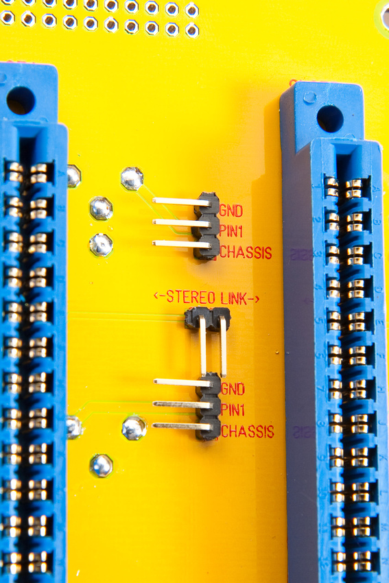
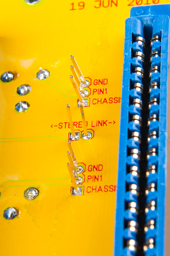
. . . and, I have plenty of clearance on the back side with these for soldering.
These would have been much easier to solder in prior to the XLR connectors going in. If building again, I would have definitely done it in that sequence, but a little patience got the job done. . . not the cleanest solders in the world but the multimeter meter tells me the joints are looking ok.
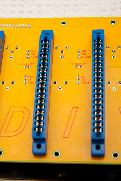
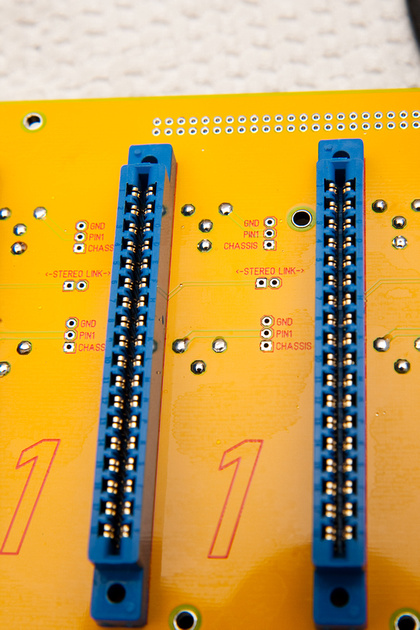
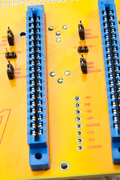
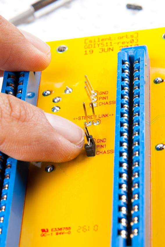
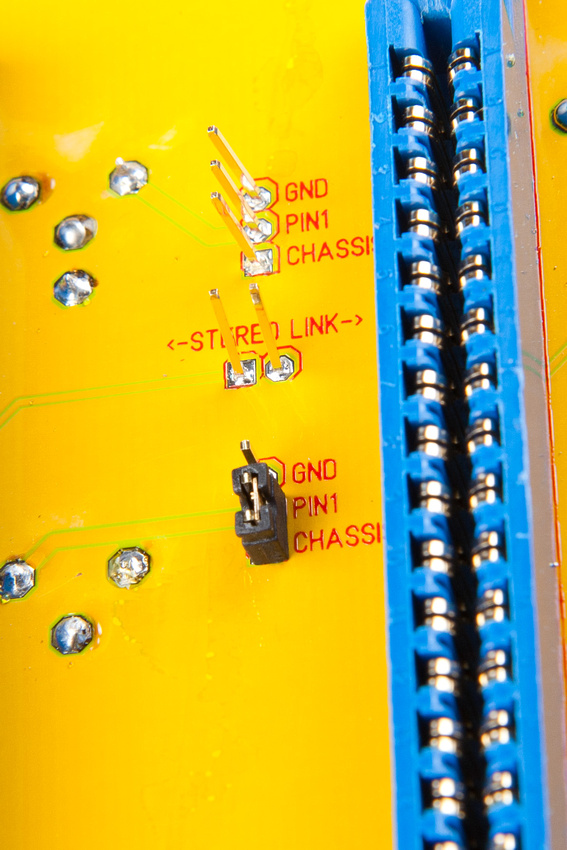
This kit allows the user to choose various grounding options with the jumpers. For now, I have pin 1 to ground, but I'll probably put pin 1 to chassis and then check to see if phantom power is working properly as my feeling I get from reading suggests this is a more "proper" way to do it. If I get noise or phantom power problems, I can change it over to the other configuration and try.
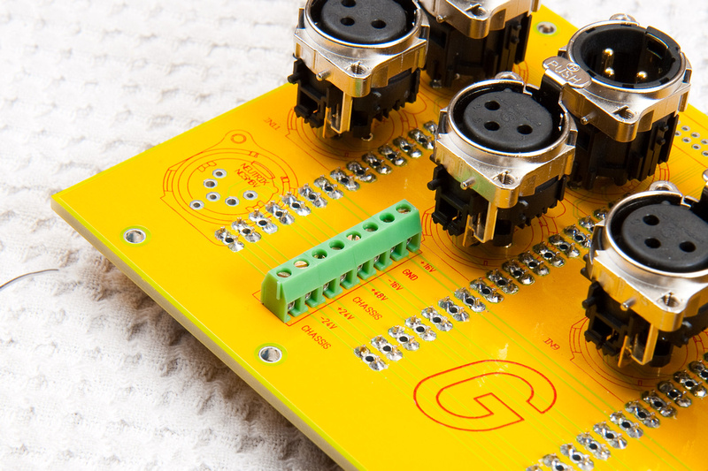
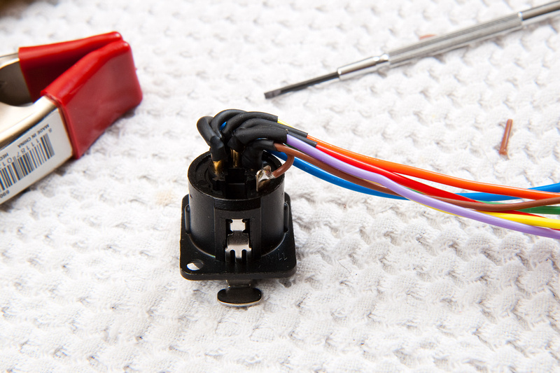
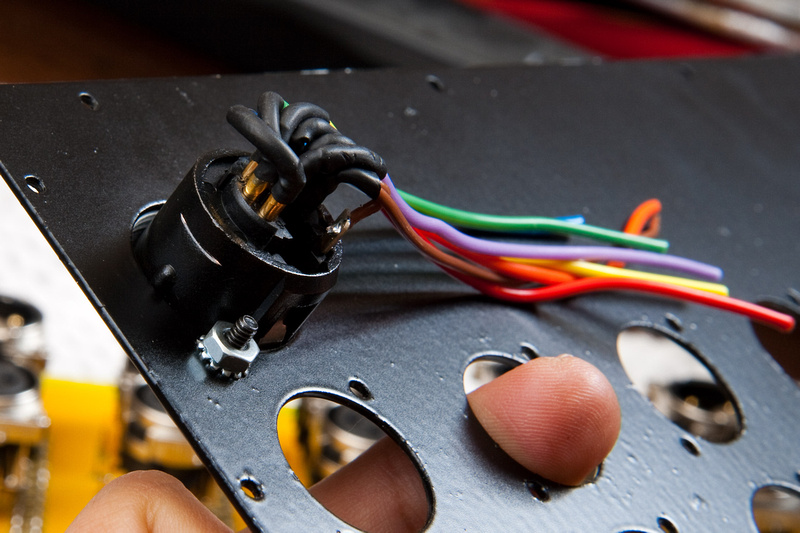
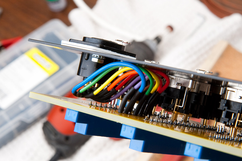
For my power connections and wiring up the 7 pin Neutrik connector, I am going to use this configuration:
pin 1 = Chassis - brown
pin 2 = Gnd - red
pin 3 = +16V - orange
pin 4 = -16V - yellow
pin 5 = +48V - green
pin 6 = +24V - blue
pin 7 = -24V - violet
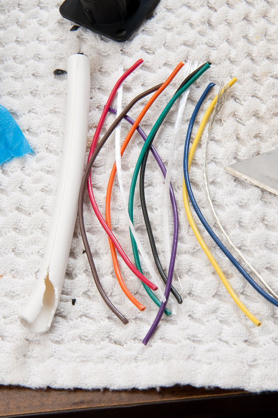
well, I guess it couldn't all go without problems. . . and the problems I had were with these connectors.
I think they were not designed to fit 16 gauge wire. And, I probably shouldn't have been using 16 for this anyways (stiff and thick), but it's the one gauge that I had in pretty colors. Next time, I'll just cut a chunk of 8 conductor 20 awg off of my 7 conductor PSU wire and split up the strands and use those for internal hookup if I want all the pretty colors.
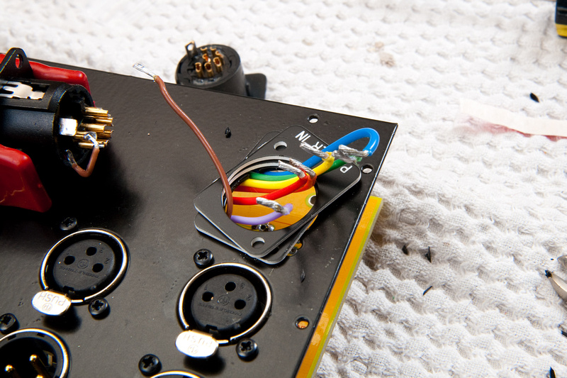
Back side of the connectors and I've changed the pin 1 grounding to chassis.
Front side
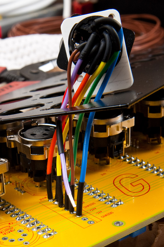
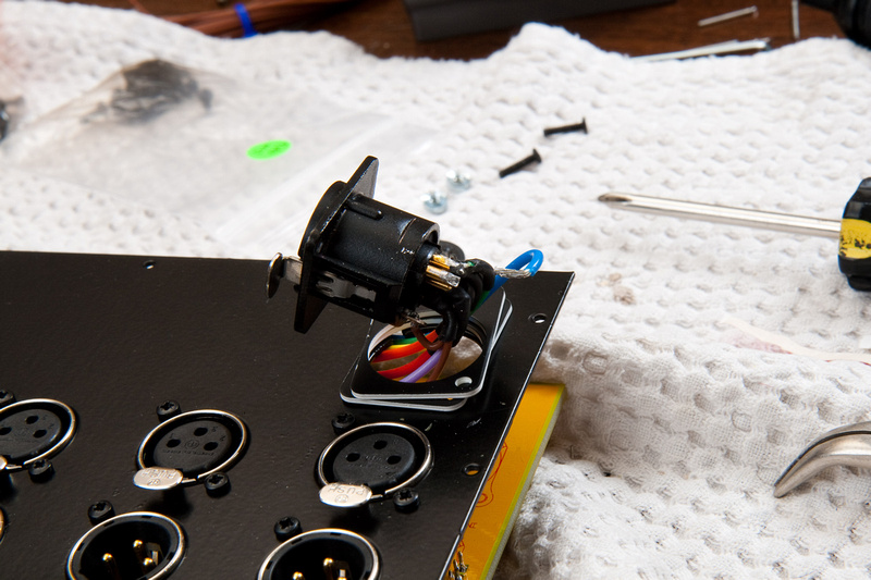
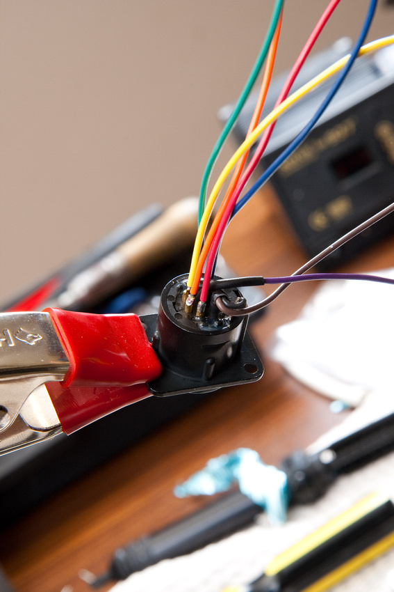
7 pin neutrik soldered up. I tried the best I could to create clearance on the back side while using the silly 16awg wire that I will not do again in this spot. I simply followed resistor color code numbering on the Neutrik pin positions. I also did a little pigtail from pin 1 on the connector (chassis) to the jack housing. I hope that's proper. I guess I'll have to look that up.
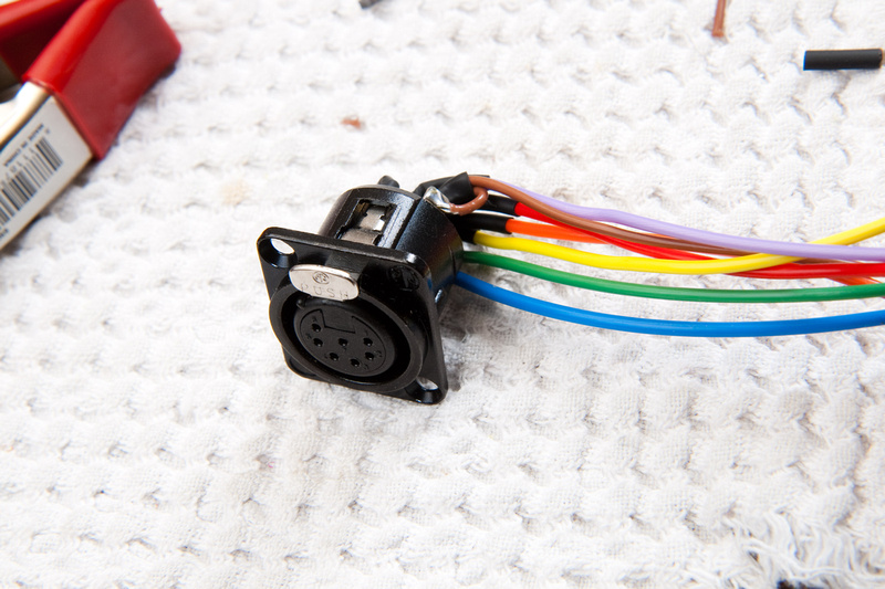
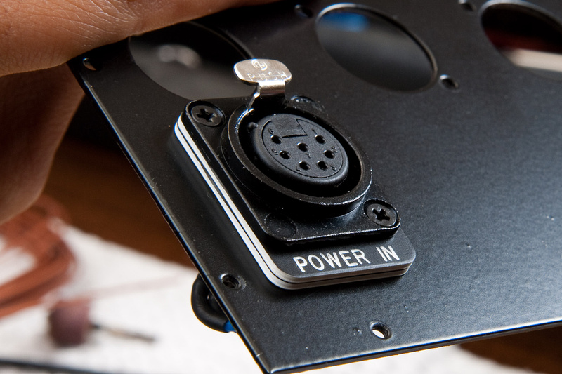
Unfortunately, I used the wrong gender connector and had to go back and change it out. The reason you should not use a female connector on the rack side is the male connector on the cable side may be hot and accidentally get shorted.
I also bought a few of these little custom Neutrik plates from Redco (they can be ordered to say whatever you want). These "spacers" will help create a little bit more clearance on the back side of the connector which is the primary reason I bought them.
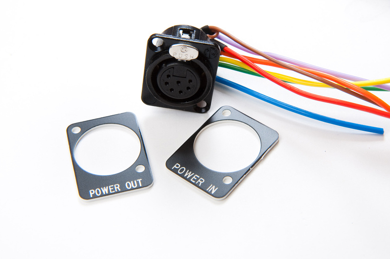
Screws for the neutrik. . . the Neutrik goes on the plate, and I decided to stack the label plates to give me a little extra wire clearance without looking ugly.
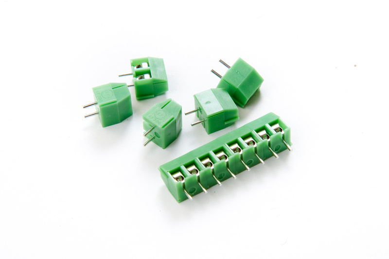
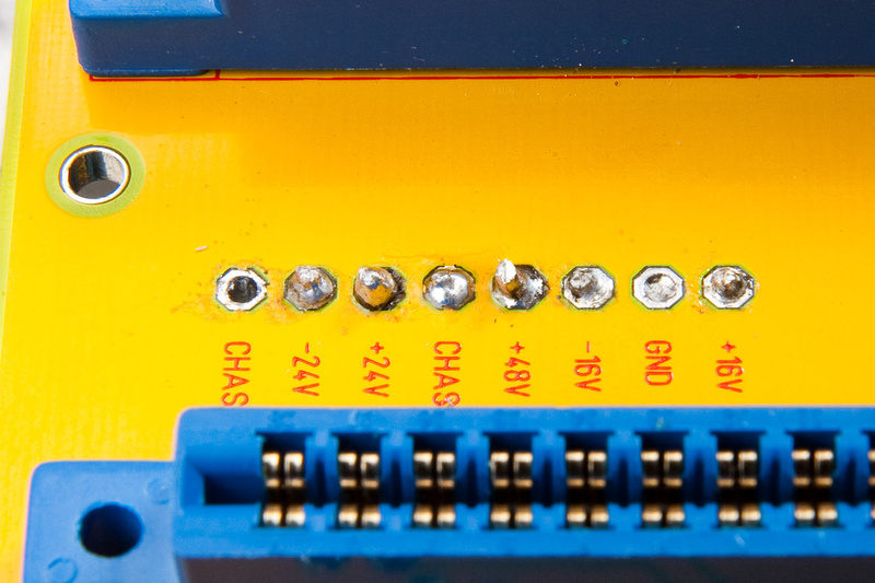
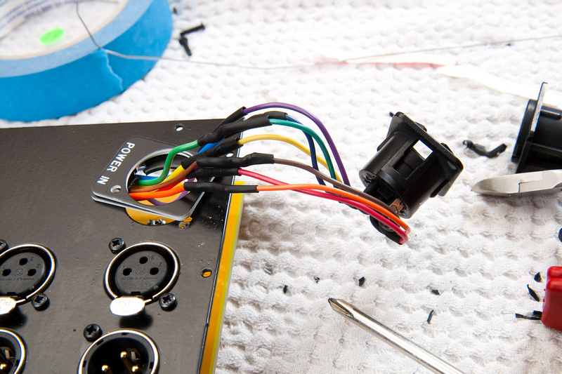
So, it was all going to be down hill from here. . . simply screw in the wires to my terminals, button everything up, and we're done. . . First problem was I did not leave enough slack on the wire tails to maneuver easily. . . next time, I should definitely leave another 2 inches or so to make things much easier. . . and then, on the 3rd wire, one of the screw terminal blocks stripped, and I was hosed. The screw did not have enough threads to clamp down with a 16 gauge wire installed.
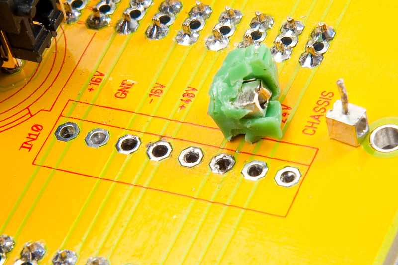
I don't have proper de-soldering equipment, so these terminals didn't come out too clean. Good thing these boards are built like tanks. I was really hoping not to utilize that particular feature

So, after this, I re-thought my strategy and decided to solder wire directly to PCB. . . The board has now been compromised so repair will be more difficult. The front side of the holes have less damage than the back side of the PCB. . . I figure with 16 gauge wire, if I ever need to go back in for repairs, and really need to remove the Neutrik, I'll just cut and splice on the installed wire as that is pretty robust.
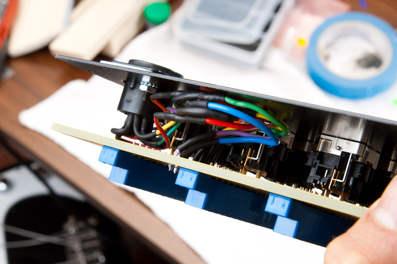
And, my final clearance is not too shaby so the spacer plan seems to have paid off.
I soldered from the front side, and this is a shot from the back side. . . not too pretty, but I'm hoping it'll hold. I poked a bit to make sure I had continuity and no weird shorts.
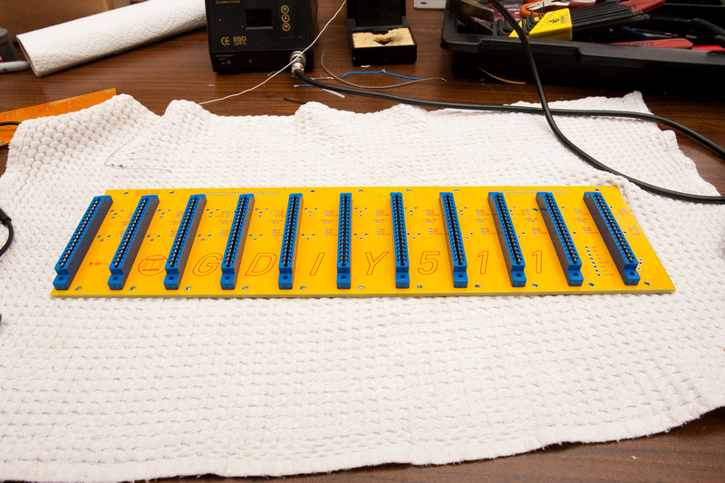
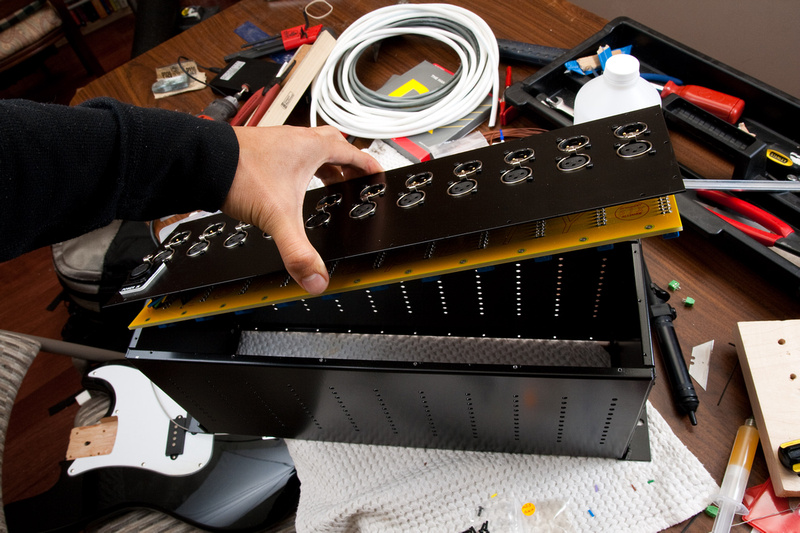
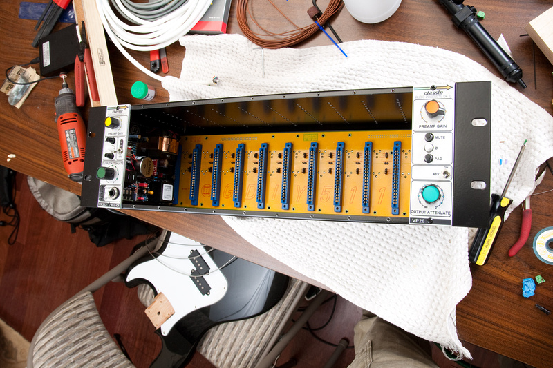
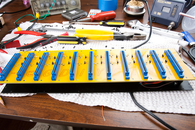
And, finally, it was time to assemble the completed rack.
And, my cat decided that the Redco box was a good place to sleep and hang out.


Quite a few m2.5 screws go in the back side. . . (the back side screws are all the same even on the perimeter)
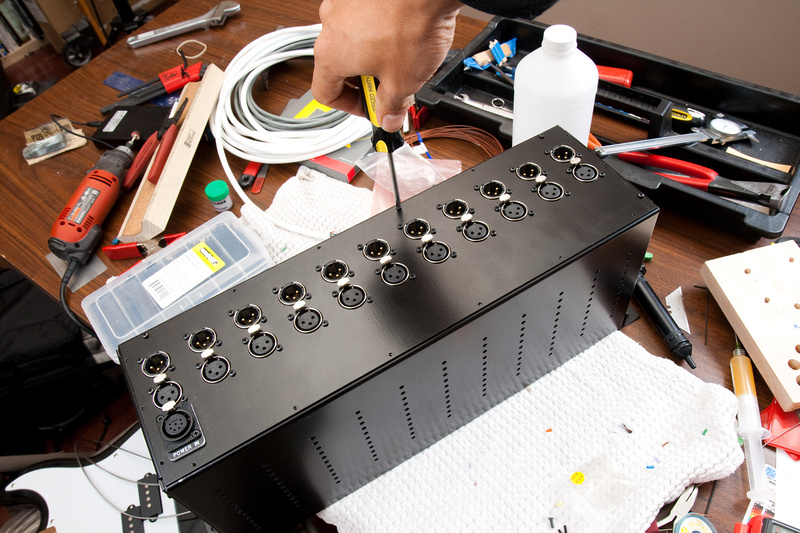
And, humans win! (except for the incorrect female neutrik power input jack that I need to change to male).
Well. . . had a bad feeling that this wasn't going to end up as clean as I like. . . on my own, I would probably have left the female Neutrik, but since I know people are watching the thread, I figure I'd better make it right even if it ends up a bit messier than I like. Guess I'll just have to buy another rack and do it right.
Old connector is off.
At this point, I realized that the male connector has much smaller wire receiver lugs for soldering, so it would be absolutely impossible to get the 16 gauge wires in. I had to go down to something smaller. This time, I did what I should have done from the beginning (would have saved my block terminals also!). . . gut a piece of my 8 conductor power wire and use the 20 awg individual wires.
And, spliced in. . .
definitely not as clean as before, but solid I think.
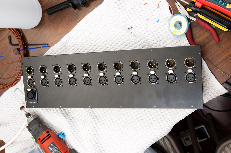
and. . . after many errors and setbacks, humans win!
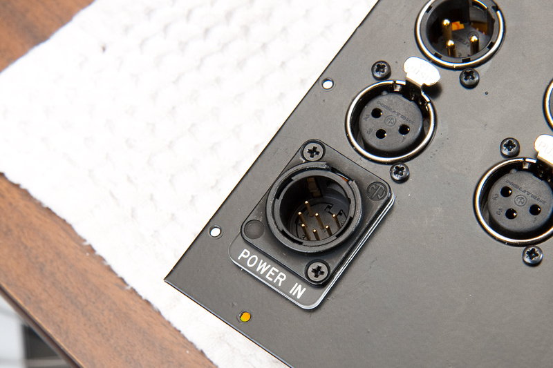
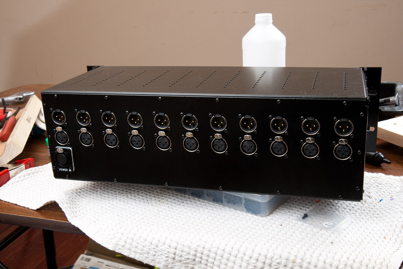
Let's try this shot again this time with the proper connector.
After running the rack for a while, I ran into a problem. Everything was working well until I built a Classic Audio Products LC53A EQ which has a full metal case as opposed to just an L-bracket like most kits I've assembled and run in the rack.
Anyways, the LC53A is built to API external dimension specs and DOES NOT fit into the GDIY51X rack as built here. Many LC53A builds I've seen run the module without its metal cover for this reason I suspect. Knowing the backplane of the rack is 1/8" thick, I figured even with the best of tools, de-soldering the headers and installing them from the back side as they should have been installed in the first place could be a nightmare.
After some head-scratching, I devised the following simple solution that is minimally invasive and 100% functional.
Remove the back panel from the 51X rack.
remove grounding jumpers.
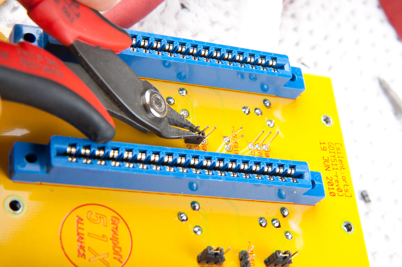
pry up the plastic portion of the headers with a screwdriver.
And pull the plastic base of the headers all the way off.
This will leave the metal portion free-standing on the PCB.
Next, re-install the jumper tight to the PCB.
And cut the leads tight to the top of the jumper.
This leaves the jumpers as close to the PCB as possible with the only drawback being slightly more difficulty inserting jumpers as the pointed guide edge is chopped off.
Continue with on with the rest of the jumpers until all are trimmed to length.
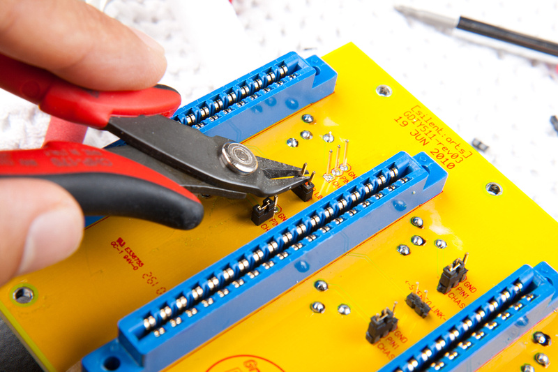
Nice and low now.
No more clearance issues whatsoever.
And that was my GDIY 511 rack build. As this was my first DIY project, there were a lot of questions I had and mistakes I made along the way that complicated the build, but in the end, I think the rack is solid and should be able to last a lifetime or more if taken care of.
Great Stuff. How much total do you think you spent on making this rack?
ReplyDeleteI believe it was around $850 for this version. I think the current version from Classic Audio Products is a little less because the metalwork is cheaper. There are also fewer internal wire runs in the design, so assembly is significantly easier.
ReplyDeleteYou're a natural at this. Reading this was your first build surprised me. You handled the jumper modification with the pragmatism and balls of a pro. Other builders (myself included) would not have had the courage to take that on on a first build. Bravo!
ReplyDeleteCat in box = my favorite part.
Great job...im tired for you!!
ReplyDeleteGreat job...im tired for you!!
ReplyDelete